Burn Firmware
This page describes how to build NinjaPCR's firmware and write it to the ESP8266 chip on the board. A USB-serial cable with 6 or 4 pins and a jumper pin is required.

Install Arduino IDE
AccessArduino.cc, then download and install the latest Arduino IDE to your PC.
https://www.arduino.cc/en/Main/Software
Install the ESP8266 add-ons
Arduino IDE doesn't support ESP8266 by default.
You need to install ESP8266 add-ons such as libraries, configuration files and build tools with the Boards Manager.
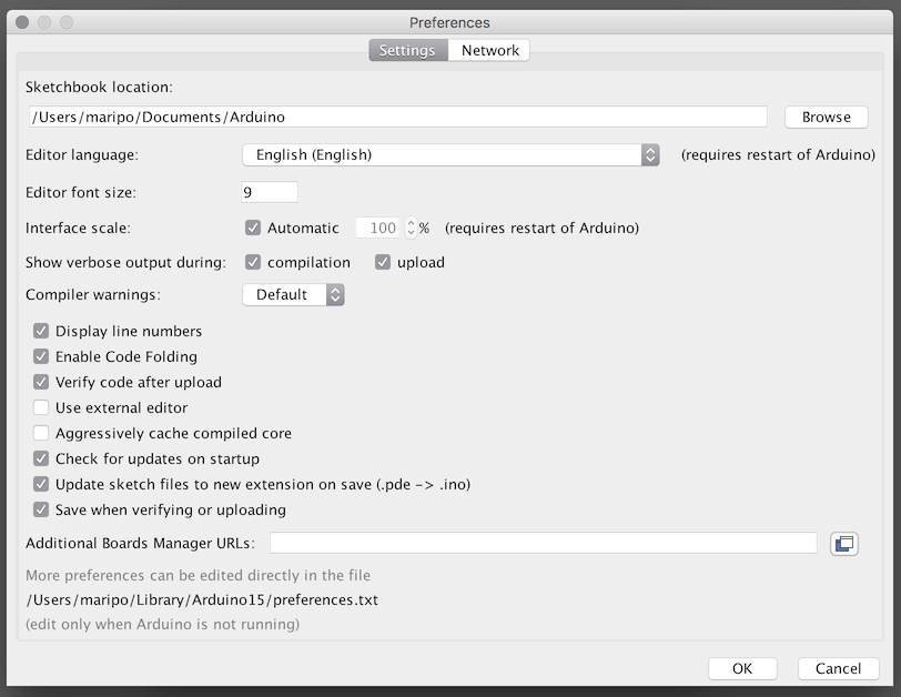
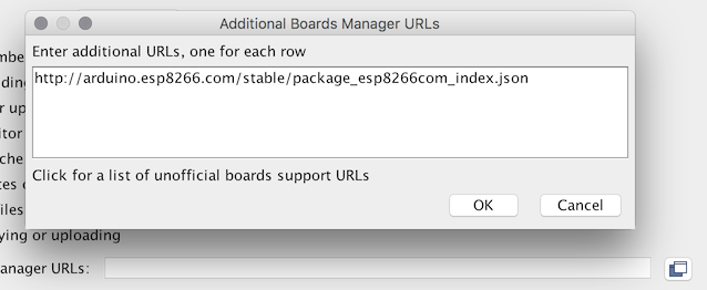
First, open "Preferences" from the Arduino's tool bar and add"http://arduino.esp8266.com/stable/package_esp8266com_index.json" tothe "Additional Board Manager URLs" textbox.
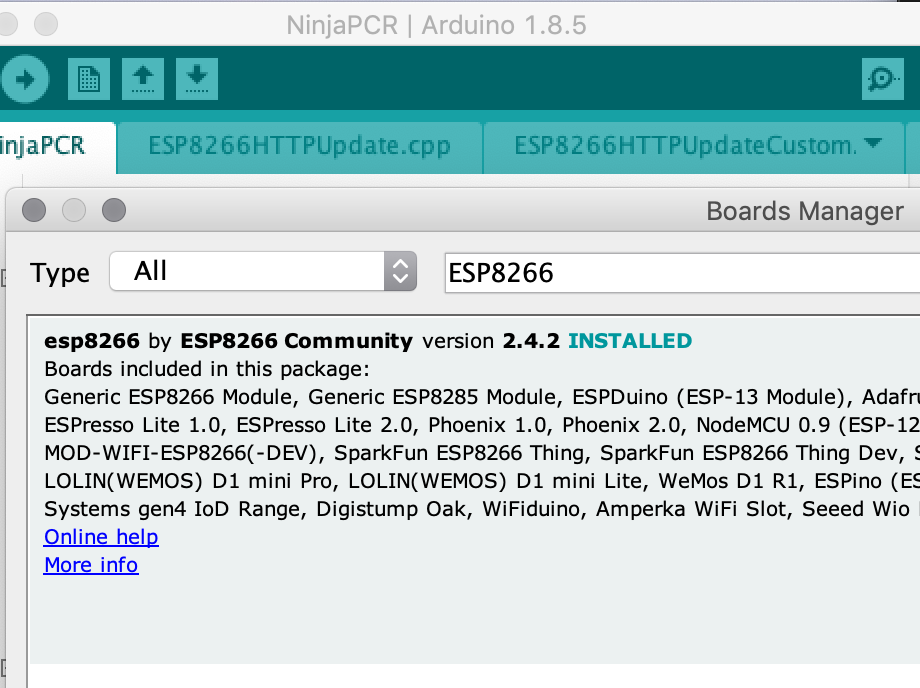
Then, select "Tools > Board: > Boards Manager..." and select "esp8266 by ESP8266 Community".If you find multiple versions, please select Version 2.4.2 or upper.
You can also install ESP8266 add-ons manually from the GitHub repository. For detailed information, please refer to the GitHub repo of ESP8266 project.
Download the source code of NinjaPCR
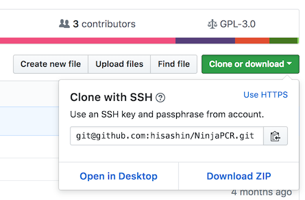
Download NinjaPCR's source code from GitHub repository. The easiest way is to download and extend the zip archive. If you are familiar with git or want to follow future updates, clone "git@github.com:hisashin/NinjaPCR.git" with git.
After downloading, open"arduino/NinjaPCR/NinjaPCR.ino"
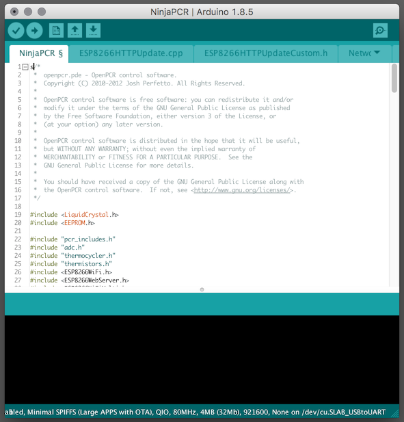
You need to select build settings for ESP8266. Open "Board" and choose "Generic ESP8266 Module".Then, choose Flash size. Note that there are variations of ESP8266. Some chips have 4MB flash memories while others have only 2MB. Select "2M (1M SPIFFS)" for the 2M model and "4M (3M SPIFFS)" for the 4MB model.
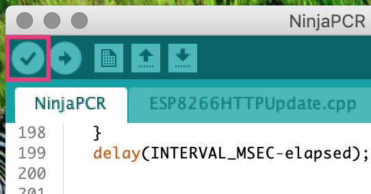
After configuration, press the "Verify" button and make sure that the source code have no problems.
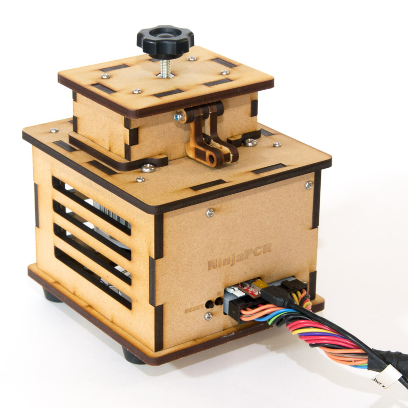
Connect NinjaPCR to your PC
Connect the power cable to NinjaPCR's connector. At this time, please do not put the plug in the outlet.
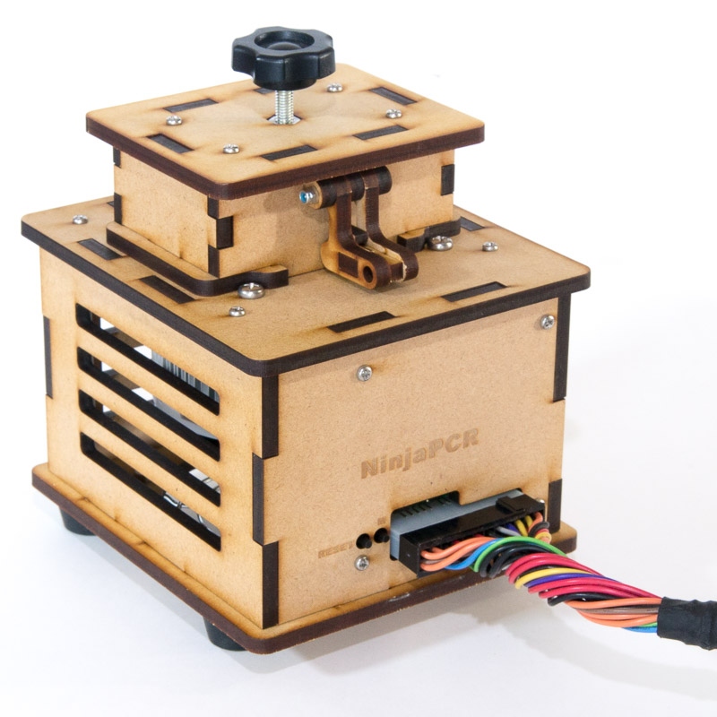
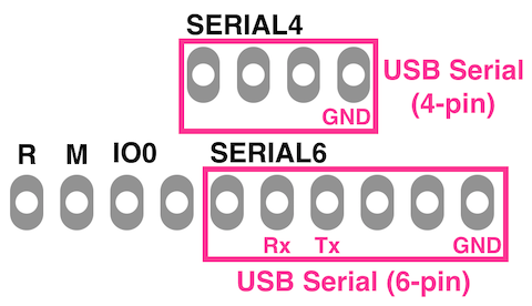
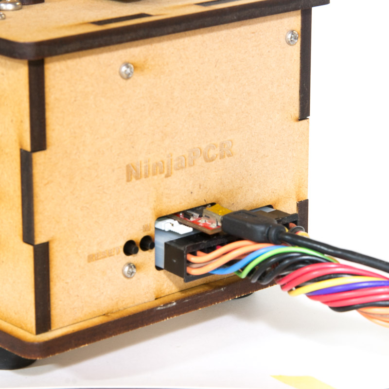
Then, connect NinjaPCR to your PC with a USB serial cable. If your cable has 6 pins, they should be attached to the right six pins on the board with the label "SERIAL 6". For 4-pin types, the board has "SERIAL 4" pins above them.
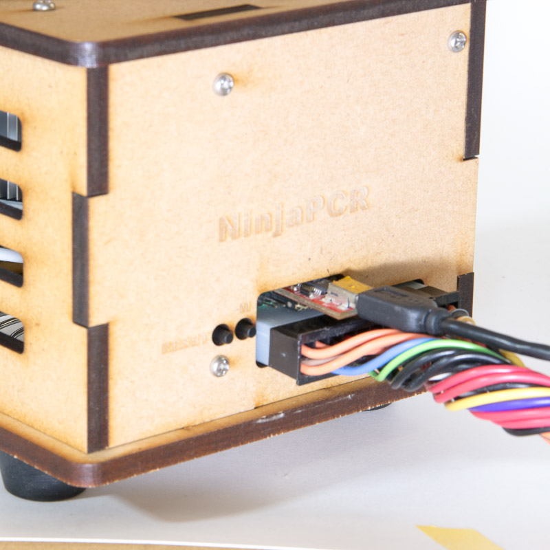
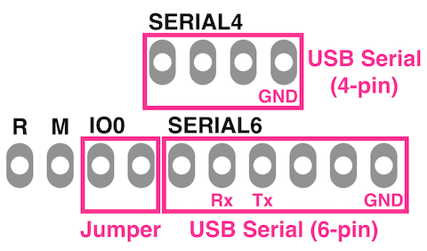
Attach a jumper pin to the two pins with the label "IO0".By turning on or resetting the board with these pins connected, you can boot the chip into the bootloader mode.
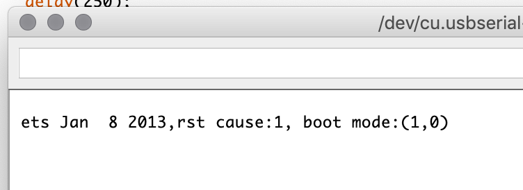
If you are not sure that the chip is really in the bootloader mode, please open the serial monitor of Arduino IDE, set the baud rateto "74880".
When ESP8266 starts with the bootloader mode correctly, the monitor displays messages as shown below:
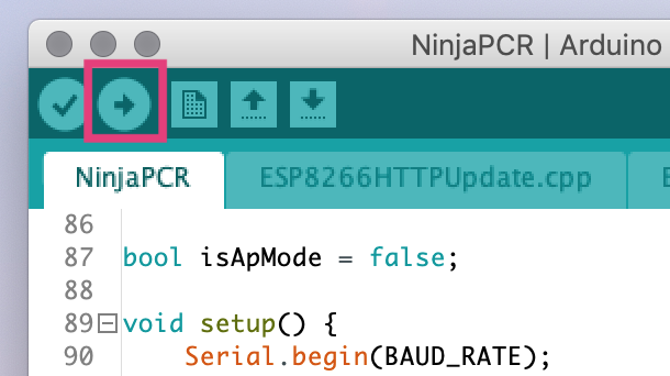
Burn!
Click the "Upload" button of Arduino IDE to build and flash the program.
If you have troubles when building or flashing with Arduino IDE, please try esptool.py from command line.
Building and flashing depend on environments such as OS, toolchains and flashing tools. If you have troubles, please contact us with detailed situation.
Debug
NinjaPCR is designed to be controllable only by Wi-Fi communication. However, a USB-serial cable is very useful to debug the program.
You can send debug messages from NinjaPCR to your PC by using serial related functions such as Serial.print() and Serial.println().
The easiest way is to use the serial monitor of Arduino IDE. Of course, you can use other serial communicator apps.
Next step : Initial Setup